


Megger MFT-X1 Multifunction Electrical Tester – Advanced Testing for Low Voltage Installations & EV Chargers
Original price was: $4,054.00.$3,800.00Current price is: $3,800.00. .( $4,180.00 inc. GST )
100 in stock
For all your equipment calibration needs, visit our MyCalibration website.
![]() Free Delivery on orders over $1000
Free Delivery on orders over $1000
Shipping time may vary for certain products*
Product Enquiry
If you would like more information regarding this product, simply email us here.
![]()
The Megger MFT-X1 Multifunction Tester delivers advanced testing capabilities for low voltage installations, including EV chargers, with user-friendly features and a rugged design. With its high-accuracy measurements and upgradeable operating system, it’s the ideal tool for electrical professionals seeking reliability and efficiency in their testing processes.
 MFT-X1 Multifunction tester Datasheet
 Electrical testing certification software
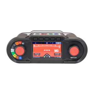
Megger MFT-X1 Multifunction Tester Overview
The Megger MFT-X1 Multifunction Tester is a state-of-the-art device designed for testing low voltage electrical installations in a variety of settings, including domestic, commercial, and industrial applications. With its extensive range of features and capabilities, the MFT-X1 stands out as a reliable tool for electrical professionals.
Megger Confidence Meter Technology: Faster and More Accurate Loop Testing
The Megger Confidence Meter technology revolutionises loop impedance testing by delivering faster, more reliable results. Supporting all loop impedance ranges, this patented technology significantly reduces test times for non-trip loop testing—down to just 7 seconds on quiet circuits. It also optimises testing in noisy electrical supplies, ensuring accurate and stable results.
The Confidence Meter actively monitors test progress and detects noise on the circuit, eliminating erroneous readings and providing consistent results every time.
Easily Download and Manage Results with the MFT-X1 and CertSuite
With the MFT-X1, installation test results can be tagged with circuit data and seamlessly transferred for efficient record-keeping. Combined with the CertSuite software, managing and certifying your test results has never been easier.
Whether you need faster testing, accurate measurements, or simplified report management, Megger tools are designed to enhance your electrical testing workflow.
[embedyt] https://www.youtube.com/watch?v=eaQvA9qHJ3Y[/embedyt] [embedyt] https://www.youtube.com/watch?v=1gdVx-UTzGM[/embedyt]Key Features
Advanced Testing Capabilities
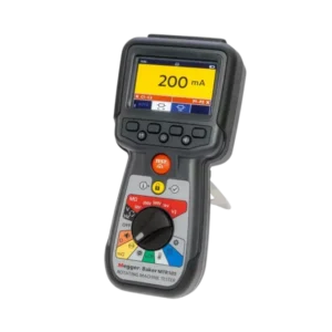
The MFT-X1 offers exceptional testing accuracy with high-resolution loop impedance testing. It enhances the low end of the impedance range with a resolution of 0.001 ohms, allowing for realistic low impedance measurements. Additionally, it provides advanced features for RCD testing, including a custom test configurator to optimise testing sequences to meet specific requirements.
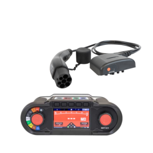
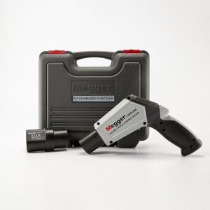
EV Charge Point Testing
As electric vehicles become more prevalent, the MFT-X1 is perfectly equipped to test EV charger installations, including both RCD Type B and RDC protected charge points. When paired with the optional Megger EVCA adaptor, the MFT-X1 can efficiently test all known EV chargers, ensuring safe and suitable installations.
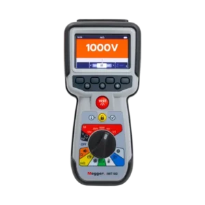
Stabilised Insulation Test Voltage
For accurate insulation testing, the MFT-X1 introduces a stabilised insulation test voltage, ensuring output voltage remains accurate within +/-2% +2 digits. This reliability mitigates the risk of over-voltage, making it especially crucial for sensitive components and circuits in various installations.
User-Friendly Interface
The device features a high-contrast 480 x 272 colour TFT bonded display that offers significant flexibility for its users. It includes a monochrome mode optimised for challenging lighting conditions, ensuring that testing can continue in less-than-ideal environments. The thoughtfully-designed user interface features hot keys for critical functions and an intuitive rotary dial for easy test selections, even when wearing gloves.
Upgradeable Operating System
The MFT-X1 ensures longevity and adaptability with its customer-upgradeable operating system. By simply downloading updates from the Megger website onto a microSD card, users can keep their device current without the need for expert assistance, thereby enhancing its ongoing usability.
Extended Applications
This multifunction tester is not limited to just one type of testing. The MFT-X1 is suitable for a wide range of applications, including:
- EV charge point testing
- Domestic PV testing
- Motor/Generator testing
- Machine testing
- Portable appliance safety testing
- Panel building and switchgear manufacturing
- Cable testing
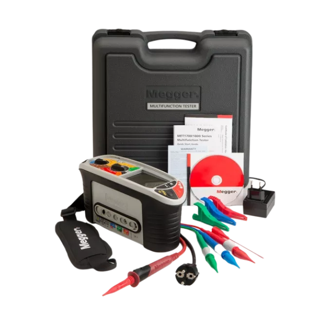
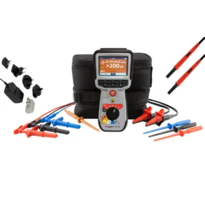
Convenient Accessories
Included with the MFT-X1 is a rugged, weather-proof carry case for excellent protection and easy transport. Additionally, a comprehensive set of test leads is provided, helping to address the complex connection requirements of modern electrical systems.
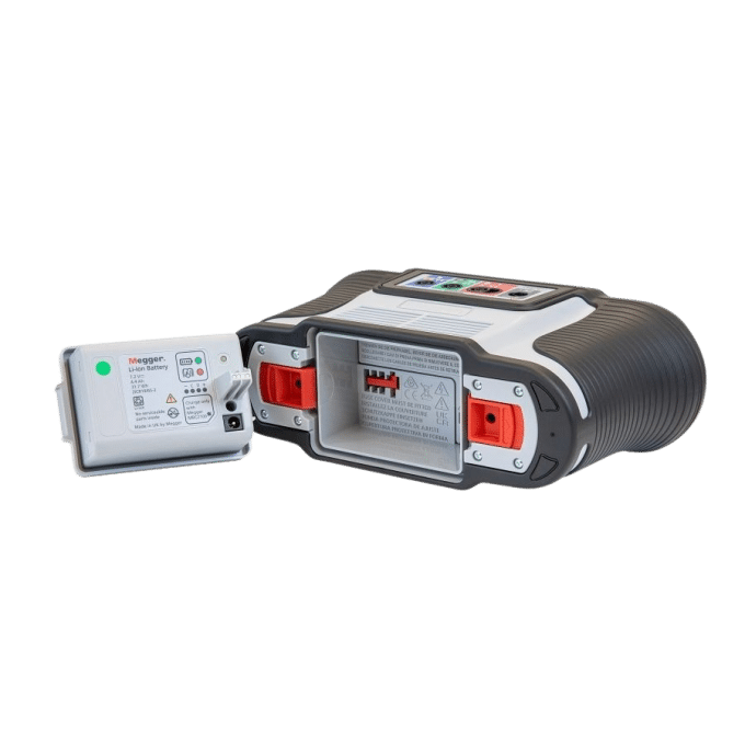
Megger MBP44 Lithium-Ion Rechargeable Battery
The Megger battery pack solution allows for easy swapping between the rechargeable 4 Ahr Li-ION pack and the AA carrier module, offering industry-leading flexibility and fast battery changes. The smart fuel tank chip technology ensures accurate battery status on the Li-ION pack.
Conclusion
The Megger MFT-X1 Multifunction Tester combines innovation, accuracy, and user-friendly design to deliver superior performance for electrical testing. Whether undertaking low voltage installations or ensuring compliance in varied applications, the MFT-X1 is the ideal choice for professionals seeking reliability and efficiency in their toolkit. Equip yourself with the MFT-X1 and experience unparalleled testing capabilities today!
| Weight | .5 kg |
|---|
Be the first to review “Megger MFT-X1 Multifunction Electrical Tester – Advanced Testing for Low Voltage Installations & EV Chargers”
You must be logged in to post a review.
FUNCTIONAL SUMMARY
|
Voltage measurement |
|
|
Voltage range |
0.001 V to 2 V (mV range) 2 V to 600 V (V range), 1000 V DC (Non-CAT rated circuits) |
|
Voltage type: |
Trms, AC, DC |
|
Phase sequence |
Automatic phase sequence testing on detection of valid three phase supplies |
|
Current measurement (non-contact) |
|
|
AC Trms |
Using optional accessories: MCC1010 current clamp |
|
Measurement Range |
MCC1010: 1 mA to 300 A |
|
Continuity/Resistance |
|
|
Measurement range Digital display |
0.01 Ω to 999 kΩ Auto-ranging |
|
Measurement Range Analogue arc |
0 Ω to 1 MΩ log scale |
|
Test voltage |
4 V DC to 5 V DC |
|
Test current (Nominal) |
>200 mA 0 Ω >< 2 Ω 10 mA Auto reduction on high resistance (actual current reported in display) |
|
Test polarities |
Forward polarity |
|
Buzzer resistance range |
> 0.01 Ω < 2 kΩ |
|
Buzzer threshold |
0.3, 0.5, 1, 2, 3, 4, 5, 10, 20, 30, 40, 50, 100, 200 Ω |
|
Insulation testing |
|
|
Measurement range Digital display |
0.001 MΩ to 999 MΩ Auto-ranging |
|
Measurement range Analogue arc |
0.001 MΩ to >1000 MΩ log scale |
|
Insulation test voltages |
50 V DC to 1000 V DC + Variable 50 V to 999 V |
|
Test current |
1 mA to 2 mA |
|
Stabilised output voltage |
Output test voltage stabilised to -0% +2% +2 V |
|
True Loop™ loop impedance testing |
|
|
2 Wire – all modes |
|
|
Test types |
Mode 1: Non-Trip |
|
Mode 2: High current |
|
|
Mode 3: High resolution |
|
|
Resolution |
Non-Trip: 0.01 Ω |
|
High current: 0.01 Ω |
|
|
High resolution: 0.001 Ω |
|
|
Voltage range |
Non-trip: 48 V AC to 280 V AC |
|
High current: 48 V AC to 550V AC |
|
|
High resolution: 48 V AC to 550 V AC |
|
|
Frequency range |
45 Hz to 65 Hz (all modes) |
|
3 Phase testing |
Non-trip: Single phase only |
|
High current: Three phase |
|
|
High resolution: Three phase |
|
|
3 wire – non-trip |
|
|
Test types |
RCD (non-trip) RCD EV (non-trip on 6mA EV RDCs) |
|
Resolution |
0.01 Ω |
|
Voltage range |
48 V AC to 280 V |
|
Frequency range |
45 Hz to 65 Hz |
|
3 Phase testing |
Single phase only |
|
Volt drop |
|
|
Volt drop calculation |
Requires Zref (Ze) and circuit current (I-vdrop) |
|
Accuracy |
Dependent on loop impedance accuracy |
|
RCD testing |
|
|
RCD types supported |
Type AC, A, B, AC(S), A(S), B(S) |
|
Auto RCD sequence |
1 / 2x I∆n, 1x I∆n, 2x I∆n, 5x I∆n, Ramp, 0º / 180º (customer configurable) |
|
Ramp testing |
10 mA to 1000 mA |
|
RDC testing |
6 mA RDC |
|
Fault (Touch) voltage |
0 V to 253 V |
|
Earth testing |
|
|
2 wire |
2 wire earth resistance test |
|
3 wire |
3 wire earth resistance |
|
3 wire ART |
3 wire testing with additional MCC1010 current clamp |
|
Stakeless |
Stakeless testing using the MCC1010 and MVC1010 clamps |
SPECIFICATIONS
Voltage measurement
|
Function |
Range |
Accuracy |
|
Voltage DC |
0 V – ±1000 V |
±1% ± 3 digits |
|
Voltage AC/TRMS |
0 V – 600 V (15 – 500 Hz) |
±2% ± 1 digits |
|
Frequency |
15 Hz – 99 Hz 100 Hz – 500 Hz |
±0.5% ± 2 digit ±2.0% ± 2 digit |
Millivolt measurement
|
Function |
Range |
Accuracy |
|
mV AC/TRMS |
0 mV to 1999 mV (50 / 60 Hz) |
±1% ± 3 digits |
|
mV DC |
0 mV to ±1999 mV |
±1% ± 3 digits |
Live Earth detection
Indicates if the PE terminal is live when selecting the Loop or RCD test ranges. The relevant Loop or RCD test is inhibited.
Current
|
Function |
Range |
Accuracy |
|
Current AC/TRMS |
0.001 A – 0.100 A |
±2% ±3 digits |
|
0.100 A – 2.000 A |
±2% ±3 digits |
|
|
2.00 A – 20.00 A |
±2% ±3 digits |
|
|
20.0 A – 300.0 A |
±2% ±3 digits |
|
|
Frequency Bandwidth |
15 Hz – 500 Hz |
|
|
Influence of Frequency |
30 Hz – 500 Hz ≤0.25 % |
|
Resistance and Continuity
|
Function |
Range |
Test Current |
Accuracy |
|
200 mA |
0.01 Ω – 99.9 Ω |
(0 Ω – 2 Ω) 205 mA ±5 mA |
±3% ±2 digits |
|
10 mA |
0.01 Ω – 99.9 Ω |
10 mA |
±3% ±2 digits |
|
100 Ω – 999 kΩ |
±5% ±2 digits |
||
|
Open circuit voltage |
4 V to 5 V |
||
EN61557-4 Measurement Range: 0.10 Ω to 999 kΩ.
Safety and electrical protection
|
Safety rating: |
CAT III 600 V / CAT IV 300 V to EN 61010, IEC 61010-031 : 2015, IEC 61010-030. |
Safety category rating valid to altitude of 2000 m. |
|
Live voltage: |
Active live voltage protection to 600 V between any test terminals without blowing a fuse. Live voltage warning on display and audible when >5 V is applied between any test terminals. Fuse protected to 1000 V, fuses are not user changeable. |
Insulation test
|
Function |
Range |
Accuracy |
|
1000 V |
0.001 – 999 MΩ |
±3% ±2 digits |
|
500 V |
0.001 – 500 MΩ |
±3% ±2 digits |
|
> 500 MΩ |
±10% |
|
|
250 V |
0.001 – 250 MΩ |
±3% ±2 digits |
|
> 250 MΩ |
±10% |
|
|
100 V |
0.001 – 100 MΩ |
±3% ±2 digits |
|
> 100 MΩ |
±10% |
|
|
50 V |
0.001 – 50 MΩ |
±3% ±2 digits |
|
> 50 MΩ |
±10% |
|
|
VAR 50 V – 999 V |
Leakage current > 1 mA |
±3% ±2 digits |
|
Leakage current < 1 mA |
±10% |
|
|
Leakage current |
0.1 µA – 1.99 mA |
±10% |
|
Output voltage |
-0% +2% +2 V at rated load or less |
|
|
Voltage display |
±1% ± 3 V |
|
|
Short circuit current |
1.5 mA nominal |
|
|
Test current on load |
1 mA at min pass values of insulation |
|
|
Maximum capacitance |
2 µF for a stable reading, 5 µF absolute limit |
|
EN61557-2 Measurement Range: 0.10 MΩ to 999 MΩ.
Loop 2-Wire – No RCD (L-PE, L-N or L-L)
|
Function |
Range |
Accuracy |
|
2-Wire HR |
0.001 – 9.999 |
±2% ±0.030 Ω |
|
2-Wire |
0.01 Ω – 9.99 Ω |
±2% ±5 digits |
|
10.0 Ω – 99.9 Ω |
±10% ±5 digits |
|
|
100 Ω – 1999 Ω |
±10% ±5 digits |
|
|
Supply Voltage |
48 V – 550 V |
|
|
Supply Frequency |
45 Hz – 65 Hz |
|
Can be used to measure supply source resistance quickly and reliably between Line and PE or two Live conductors up to 550 V.
EN61557-3 Measurement Range: 0.30 Ω to 1999 Ω
Loop 2-Wire L-PE with RCD
|
Function |
Range |
Accuracy |
|
0.01 Ω – 1999 Ω |
±10% ±5 digits |
|
|
Supply Voltage |
48 V – 280 V |
|
|
Supply Frequency |
45 Hz – 65 Hz |
|
Note: Uses the Megger Confidence Meter to measure the supply source impedance of circuits protected with an RCD rated
≥30 mA when there are only two connections possible. When a neutral is available the three-wire test will provide a quicker, more accurate result.
Note: RCD may trip if there are high leakage currents in the circuit under test. This measurement is immune to the effect of inductance found in some RCDs as it measures resistance (RCD Uplift).
EN61557-3 Measurement Range: 1.00 Ω to 1999 Ω
Loop 3-Wire L-PE with RCD
|
Designation |
Test Current |
Application |
|
RCD |
15 mA |
For circuits protected by an RCD rated <= 30 mA |
|
RDC EV |
3 mA |
For EV charger circuits protected by a RDC and a Type A RCD rated <= 30 mA |
|
Function |
Range |
Accuracy |
|
0.01 Ω – 9.99 Ω |
±2% ±5 digits |
|
|
10.0 Ω – 199 9 Ω |
±10% ±5 digits |
|
|
Supply Voltage |
48 V – 280 V |
|
|
Supply Frequency |
45 Hz – 65 Hz |
|
Note: Uses the Megger Confidence Meter to measure the supply source impedance of circuits protected with an RCD when three connections are possible. The L-N Loop resistance needs to be less than 12 Ω. The resistances of the L-PE, L-N and N-PE loops
are all shown, and the accuracy of the L-PE resistance depends on the maximum resistance displayed. When the neutral is not available the two-wire test must be used.
Note: RCD may trip if there are high leakage currents in the circuit under test. This measurement is immune to the effect of inductance found in some RCDs as it measures resistance.
EN61557-3 Measurement Range: 1.00 Ω to 1999 Ω
RCD Tests Types A and AC
|
RCD Types |
AC, A, AC(S), A(S) |
|
RCD Rated Current (IΔn) |
10 mA, 30 mA, 100 mA, 300 mA, 500 mA, 650 mA, 1000 mA, VAR |
|
½ I no-trip Test Current |
-10% – +0% 0.5 IΔn |
|
1 I, 2 I, 5 I trip test – AC current |
-0% – +10% M • IΔn |
|
1 I, 2 I, 5 I trip test – pulsed DC current |
-0% – +10% 1.4 • M • IΔn |
|
Trip time |
±10% |
|
Ramp trip test current |
±5% |
|
Fault Voltage (0 V – supply) |
+5% +15% ±0.5 V |
|
Supply Voltage |
48 V – 280 V |
|
Supply Frequency |
45 Hz – 65 Hz |
Type B
|
RCD Types |
B, B(S) |
|
RCD Rated Current (IΔn) |
10 mA, 30 mA, 100 mA, 300 mA, 500 mA |
|
½ I no-trip Test Current |
-10% – +0% (0.5 IΔn) |
|
1 I, 2 I, 5 I trip test Current |
-0% – +10% (2 IΔn) |
|
Trip time |
±10% |
|
Trip current (ramp) |
±5% |
|
Fault Voltage (0 V – supply) |
+5% +15% ±0.5 V |
|
Supply Voltage |
48 V – 280 V |
|
Supply Frequency |
45 Hz – 65 Hz |
RDC (Type EV) with a 30 mA Type A RCD
|
Test current |
2.0 mA increasing to 6.3 mA before being held at that current for 10s. |
|
Trip time |
±1% ±1 ms |
|
Trip current (ramp) |
± 5% |
|
Fault Voltage (0 V – supply) |
+5% +15% ±0.5 V |
|
Supply Voltage |
48 V – 280 V |
|
Supply Frequency |
45 Hz – 65 Hz |
Earth
|
Function |
Range |
Accuracy |
|
2-Wire test |
0.01 Ω – 1999 Ω |
±2% ±3 digits |
|
Test Frequency |
128 Hz |
|
|
Test Current |
4.5 mA |
|
|
Maximum auxiliary electrode resistance (3-wire test) |
5 kΩ |
|
Note: The 2-wire earth test measures resistance between the blue and green terminals using a 128 Hz square wave; the result includes the resistance of test leads.
EN61557-5 Measurement Range: 1 Ω to 1999 Ω.
|
Function |
Range |
Accuracy |
|
3 wire test |
0.01 Ω to 1999 Ω |
±2% ±3 digits |
|
Test frequency |
128 Hz |
|
|
Test current |
25 V, 4.5 mA |
|
|
Maximum auxiliary electrode resistance |
5 kΩ for 25V |
|
|
Function |
Range |
Accuracy |
|
3P ART |
0.01 Ω to 1999 Ω |
±5% ±3 digits |
|
Test frequency |
128 Hz |
|
|
Test current |
25 V, 4.5 mA |
|
|
Minimum test current through the clamp |
5 % |
|
|
Maximum auxiliary electrode resistance |
5 kΩ for 25V or 100 kΩ for 50 V |
|
EN 61557-5 Measurement Range: 1 Ω to 1999 Ω.
|
Function |
Range |
Accuracy |
|
Stakeless |
1.0 Ω to 60 Ω |
±7% ±5 digits |
|
Test frequency |
128 Hz |
|
EN 61557-5 Measurement Range: 1.00 Ω to 40.0 Ω.
Power supply
|
Li-ion rechargeable |
7.2 V DC 4400 mAh (non-serviceable) + charge status indication |
|
Battery charger (Li-ion) |
Input: 110 V / 230 V AC, 50/60Hz, 1.3 A Output: 3 A, 8.4 V DC |
|
Battery life (Li-ion) |
Li-ion: 4400 mAh = >15 hrs* Continuity: Approximately 2000 tests using Li-ion battery (0.5s test every 30s per EN 61557) Insulation: Approximately 1400 tests using Li-ion battery (0.5s test every 30s per EN 61557) Earth: Approximately 1600 tests using Li-ion battery *times based on typical daily test profile |
|
Battery charging time |
Li-ion: 2.5 to 3 hrs (ambient temperature dependent) |
|
LR6 (AA) battery module |
8 x LR6 (AA) Alkaline batteries |
Environmental
|
Conditions |
Range |
|
Operating Temperature |
-10 °C to +55 °C |
|
Storage Temperature |
-25 °C to +70 °C |
|
Operating Humidity |
90% R.H. at +40 °C max |
|
Ingress Protection |
IEC 60529: IP 54 : Equipment is protected against ingress of dust and water splashes and is suitable for indoor and outdoor use. |
|
Vibration |
MIL-PRF-28800F:class 2 |
|
Maximum operating altitude |
2000 m |
|
Pollution degree |
2 |
Mechanical
|
Length |
274 mm (10.79 ”) |
|
Width |
96 mm (3.78 ”) |
|
Depth |
143 mm (5.63 ”) |
|
Weight – Instrument only |
1.57 kg (3.46 Ib) |
|
Shipping weight |
5.6 kg (12.35 ib) |
- True Loop™ test with patented Confidence Meter™
- CertSuite Installation compatible Bluetooth® result transfer
- Next generation 2-wire and 3-wire non-trip loop testing
- User upgradeable operating system
- High resolution 0.001Ω loop test
- Automatic volt-drop measurement
- Stabilised insulation test voltage
- Configurable RCD and EV auto-sequence tests
- Fast switch rechargeable plug-in battery pack
- Full colour TFT bonded display
- Re-designed lead set and carry case solution
- IP54 operational housing
Installation Testers
Installation Testers
Installation Testers
Installation Testers
Installation Testers
Installation Testers
Installation Testers
Installation Testers
Installation Testers
Installation Testers Related Products


Next day delivery
Finance services
Price Match
Technical support
Product training
Calibration servises
Need help? Call our support team 1800 358 531


Reviews
There are no reviews yet.