



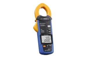
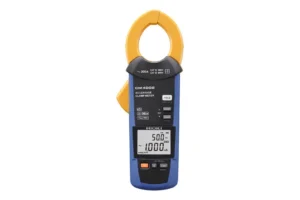
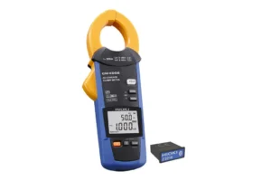
Hioki CM4002 AC Leakage Clamp Meter — Find Nuisance RCD Trips Down to 0.001 mA
$990.00 .( $1,089.00 inc. GST )
For all your equipment calibration needs, visit our MyCalibration website.
 Free Delivery on orders over $1000
Shipping time may vary for certain products*

Product Enquiry
If you would like more information regarding this product, simply email us here.

Chasing a safety switch that trips at 3am? The Hioki CM4002 AC Leakage Clamp Meter resolves earth leakage faults from 0.060 mA right through to 200 A load current, without pulling a single conductor out of the board. A Ø40 mm jaw swallows a full three-phase-plus-neutral bundle, a 180 Hz filter strips out inverter noise, and IEC/EN 61557-13 Class 2 compliance backs every reading. CAT IV 300 V / CAT III 600 V. Ready to test out of the box.

 Clampmeters Brochure
The fault that never happens while you’re standing there
Every sparky knows the job. The safety switch on the shop’s power circuit drops out twice a week, always after hours, never when you’re on site. You reset it, test it with an RCD tester, everything passes, and you leave. Two days later the phone rings again.
Intermittent earth leakage is one of the most expensive faults in Australian electrical work, because the cost isn’t in the repair — it’s in the return visits, the lost stock in a cold room, the production line that stopped, and the customer who starts to wonder whether you actually know what you’re doing.
The reason it’s so hard to pin down is simple physics. Under AS/NZS 3000, RCD protection is now standard across most final subcircuits, and a 30 mA device is permitted to operate anywhere between 50% and 100% of its rated residual current. That means a board sitting at 18 mA of standing leakage isn’t faulty — it’s just one kettle, one damp motor winding, or one extra inverter away from tripping. A pass/fail RCD tester will never show you that. You need to see the actual number, and you need to see it while the plant is running.
That’s exactly the job the Hioki CM4002 AC Leakage Clamp Meter was built for.
What the CM4002 actually does
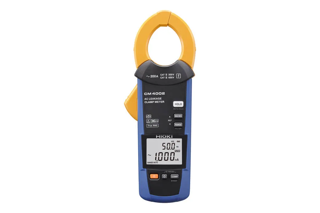
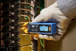
The CM4002 is a dedicated true-RMS earth leakage clamp meter. Instead of measuring current in one conductor, you clamp all the live conductors of a circuit together — active and neutral on a single-phase final subcircuit, or all three phases plus neutral on a 415 V feeder. Under healthy conditions those currents cancel, and the meter reads close to zero. Whatever’s left over is the vector sum: current that has found a path back to earth. That’s the zero-phase current, and it’s the same quantity the RCD upstream is watching.
Six ranges span 6.000 mA, 60.00 mA, 600.0 mA, 6.000 A, 60.00 A and 200.0 A, with a defined accuracy range from 0.060 mA to 200.0 A. The bottom range resolves to 0.001 mA. That span matters more than it looks: the same instrument that resolves a microamp-level insulation problem in a control cabinet can also read the 80 A load current on the feeder beside it, so you’re not swapping tools mid-diagnosis.
Basic accuracy is ±1.0% rdg ±5 dgt from 45 Hz to 400 Hz across the 6.000 mA to 6.000 A ranges — comfortably inside the band where a 50 Hz Australian installation lives.
Readings you can defend, backed by IEC/EN 61557-13
Any clamp will show you a number. The question is whether that number survives scrutiny when you put it in a report.
Hioki designed the CM4002’s current transformer specifically to answer that. The core and shielding are built from high-permeability magnetic materials and the CT is wound with a uniform coil, and the instrument complies with IEC/EN 61557-13 Class 2, 30 A/m — the international performance standard written specifically for leakage clamp meters. Three practical consequences follow:
Position inside the jaw stops mattering. Sensitivity is uniform across the aperture, so a fat two-core bundle jammed against one side of the jaw reads the same as one perfectly centred. In a densely wired distribution board, “perfectly centred” is a fantasy.
Neighbouring busbars stop lying to you. Shielding blocks external magnetic fields, with the effect of a 400 A/m external field at 50/60 Hz specified at 4 mA or less. When you’re clamping a 15 mA leakage path 50 mm away from a loaded 415 V busbar, that specification is the difference between a diagnosis and a guess.
Inverter noise can be filtered out. A switchable low-pass filter with a −3 dB point at 180 Hz ±30 Hz strips high-frequency capacitive leakage from variable speed drives, solar inverters and switch-mode supplies. This is the feature that quietly earns its keep on modern sites. The EMC filters inside a VSD or a PV inverter dump genuine — but harmless — high-frequency current to earth. An unfiltered clamp adds all of it to the reading and sends you hunting a fault that doesn’t exist. With the filter on, the CM4002 sees the installation roughly the way a Type AC or Type A RCD sees it: at power frequency, where tripping decisions are actually made.
Ø40 mm jaw, built for real switchboards
The jaw opens to a Ø40 mm conductor diameter with jaw dimensions of 75 mm × 20 mm. That’s enough to take a three-phase-plus-neutral bundle on a submain, a large single cable, or several smaller circuits at once when you’re bisecting an installation to isolate the offending branch. Undersized jaws are the most common reason a leakage clamp ends up unused in the back of a ute — this one goes where the work is.
Catching the fault that only happens at 3am
This is where the CM4002 separates itself from a basic leakage clamp.
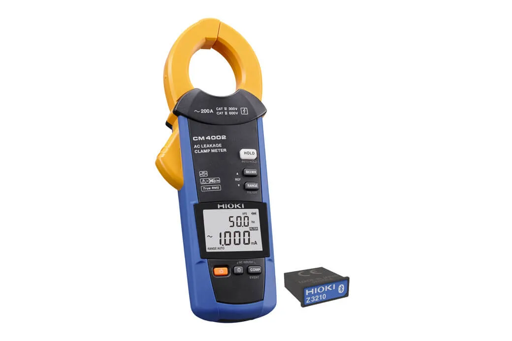
Fit the optional Z3210 Wireless Adapter and the meter gains Bluetooth®, connecting to Hioki’s free GENNECT Cross app on a phone or tablet. Two workflows open up:
Event recording. Set a leakage threshold and a recording window, clamp the meter onto the suspect circuit, and walk away. The instrument logs trip start times, trip stop times and maximum current values to internal memory — up to 999 events, over a recording period of up to 30 days (battery life permitting). You don’t need to stay connected to the tablet while it records. Come back, pull the data into GENNECT Cross, and you have a timestamped picture of an intermittent fault that no amount of standing in front of a switchboard would ever have given you.
Photo drawing for routine inspections. Photograph the board, then tap measurement locations on the image and drop the live readings onto the photo. Work upstream to downstream, and the fault location builds itself visually as you go. You can export a PDF report on site, before you’ve left the customer’s car park — which does more for repeat work than any amount of marketing.
With the Z3210 fitted, GENNECT Cross will also display current harmonics up to the 30th order, along with content factor and total harmonic distortion — useful context when leakage and power quality problems are tangled together on the same site.
Prefer to leave the phone in your pocket? The Excel® Direct Input function types measured values straight into a spreadsheet on a connected device each time auto-hold captures a reading. For calibration technicians and facilities teams doing scheduled runs across dozens of circuits, that’s an entire transcription step — and an entire class of transcription error — deleted.
The details that matter on a long day
- Dual readout shows current and frequency simultaneously, so you can spot straight away when a reading is dominated by something other than 50 Hz.
- Auto hold waits for the value to stabilise, then locks it — for when the meter is at arm’s length inside a board and the display isn’t.
- Comparator gives audible and visual pass/fail against a threshold you set. Eyes stay on the work, not the screen.
- Max / Min / AVG / PEAK MAX / PEAK MIN capture, plus inrush current measurement for motor and transformer starts.
- 48 hours of continuous running on two AA alkalines (about 30 hours with the Z3210 fitted and communicating). Batteries you can buy at any servo in the country.
- −10°C to 65°C operating range — a roof cavity in a Mildura February, or a cool store in a Tasmanian winter.
- 400 g and 233 mm long, with the C0203 carrying case included.
Where it earns its keep in Australia
Electrical contractors tracing nuisance safety switch trips in retail, hospitality and residential switchboards — measuring standing leakage before it becomes a callback, and quantifying how close a board is running to its 30 mA limit.
Industrial maintenance teams on VSD-heavy plant, where the filter function separates genuine insulation degradation from the capacitive leakage that drives are supposed to produce.
Solar installers verifying leakage behaviour on grid-connected PV systems, where inverter EMC filters, long DC runs and damp roof penetrations all contribute earth current — and where the difference between a real AS/NZS 5033 insulation problem and normal system leakage needs to be established quickly.
Facility managers and safety officers building a documented leakage baseline across a site, so that next year’s figures mean something. Earth leakage current measurement is also used in in-service testing work under AS/NZS 3760 alongside insulation resistance testing, particularly on equipment where a standard insulation test isn’t appropriate.
TAFEs, RTOs and engineering departments teaching residual current theory with an instrument that demonstrates the concept properly — including why jaw position and external fields matter, using a meter engineered to defeat both.
Choosing between the CM4002, CM4003 and CM4001
The CM4002 and CM4003 share the same sensor, the same six ranges and the same IEC/EN 61557-13 Class 2 compliance. The differences are about where you work:
- CM4002 carries the higher safety rating — CAT IV 300 V and CAT III 600 V conductor-to-ground. If you work at the origin of an installation, at the main switchboard, or on service and metering equipment, this is the model to specify.
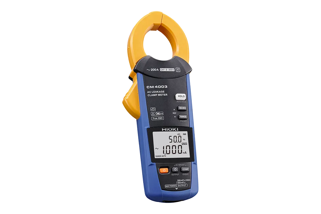
- CM4003 trades safety category down to CAT III 300 V but adds an analogue output (RMS and waveform) for feeding a recorder or Memory HiCorder, plus external DC power for unattended recording that outlasts a set of batteries.
- CM4001 is the entry point in the family, with a lower event memory capacity.
For general field work in Australian installations — where a 415 V three-phase system sits at roughly 240 V phase-to-earth, and where you’re regularly working upstream of the main switch — the CM4002’s CAT IV 300 V rating is the sensible default. As always, confirm the measurement category against your own risk assessment and the specific point of the installation you’re working on.

Ready to test out of the box
Every CM4002 ships with the C0203 carrying case, instruction manual, operating precautions and two AA alkaline batteries. Order the CM4002-90 if you want the Z3210 Wireless Adapter bundled from day one — for anyone doing intermittent fault work, it’s the version to get.
We’re a specialist test and measurement supplier, not a general tool shop. That means we can talk you through whether the CM4002 or the CM4003 fits your work, sort out calibration and recertification when it’s due, and keep you supplied with the accessories that actually get used. Got a leakage problem you can’t pin down? Talk to us before you order — we’d rather sell you the right instrument once.
Technical Specifications
| Specification | Value | Why It Matters |
|---|---|---|
| Measurement type | AC current only, true RMS | Reads distorted real-world waveforms accurately — no averaging error on non-linear loads |
| AC current ranges | 6.000 mA / 60.00 mA / 600.0 mA / 6.000 A / 60.00 A / 200.0 A (6 ranges) | One instrument covers microamp leakage through to feeder load current |
| Defined accuracy range | 0.060 mA to 200.0 A | Specified performance across the whole span, not just mid-scale |
| Best resolution | 0.001 mA | Resolves leakage changes long before an RCD reacts |
| Basic accuracy (45 Hz–400 Hz) | ±1.0% rdg ±5 dgt (6.000 mA to 6.000 A); ±1.5% rdg ±5 dgt (60.00 A, 200.0 A) | Defensible figures at 50 Hz for compliance reporting |
| Accuracy (15–45 Hz, 400 Hz–2 kHz) | ±2.0% rdg ±5 dgt | Still specified outside power frequency for drive and harmonic work |
| Frequency measurement | 15.0 Hz to 2000 Hz | Identify whether leakage is at 50 Hz or driven by switching noise |
| Low-pass filter | −3 dB at 180 Hz ±30 Hz | Strips inverter and VSD capacitive leakage so readings reflect what the RCD sees |
| External magnetic field immunity | ≤4 mA error at 400 A/m, 50/60 Hz | Reliable readings inside crowded switchboards near loaded busbars |
| Standards compliance | IEC/EN 61557-13: Class 2, 30 A/m | Performance verified against the international standard for leakage clamps |
| Safety / EMC standards | Safety: EN 61010 (type A current sensor); EMC: EN 61326 | Designed and tested to recognised international safety and EMC requirements |
| Measurement category | CAT IV 300 V / CAT III 600 V (conductor-to-ground) | Rated for work at the origin of installation and main switchboards |
| Crest factor | 3 (all ranges except 200.0 A); 1.5 on 200.0 A | Handles peaky non-sinusoidal leakage without clipping |
| Core jaw diameter | Ø40 mm (1.57 in.) | Takes a three-phase-plus-neutral bundle or a large single cable |
| Jaw dimensions | 75 mm × 20 mm | Fits between adjacent circuits in a tightly packed board |
| Display refresh rate | 5 times per second | Fast enough to see leakage move as loads switch |
| Functions | Max / Min / AVG / PEAK MAX / PEAK MIN, display hold and auto hold, backlight, auto power save, buzzer, event count display, comparator, simple event recording, inrush current measurement | Covers diagnostic and routine inspection workflows without accessories |
| Harmonics (with Z3210) | Current harmonics to 30th order, content factor, THD via GENNECT Cross | Links leakage investigation to power quality context |
| Event recording (with Z3210) | Up to 999 events; recording period up to 30 days (battery dependent) | Captures intermittent faults unattended, over weeks |
| Wireless | Optional Z3210 Wireless Adapter (Bluetooth®) | Data to phone/tablet, PDF reports on site, Excel® Direct Input |
| Power supply | 2 × AA alkaline (LR6) | Replaceable anywhere, no proprietary pack |
| Battery life | Approx. 48 h; approx. 30 h with Z3210 communicating | Multi-day jobs without a battery change |
| Operating temperature | −10°C to 65°C | Roof cavities, plant rooms and cool stores all covered |
| Operating humidity | ≤80% RH (−10 to 40°C); ≤60% RH (40–45°C); ≤50% RH (45–65°C), non-condensing | Defined limits for hot, humid Australian conditions |
| Storage temperature | −30°C to 70°C | Survives a ute toolbox |
| Ingress protection | IP40 (jaws closed) | Dust-protected for indoor work; not rated for wet exposure |
| Operating environment | Indoors, pollution degree 2, altitude ≤2000 m | Defines the intended use environment |
| Dimensions | 64 mm W × 233 mm H × 37 mm D | Slim enough to work between cables in a board |
| Weight | 400 g | Light enough for extended overhead work |
| Accuracy guarantee | 1 year | Sets the recommended recalibration interval |
| Included accessories | Carrying case C0203, instruction manual, operating precautions, 2 × AA alkaline batteries | Ready to test out of the box |
| Model variants | CM4002 (meter only); CM4002-90 (with Z3210 Wireless Adapter) | Choose standalone or wireless-enabled from day one |
Specifications sourced from Hioki CM4002/CM4003 catalogue (rev. CM4002_CM4003E6-3ZE) and the Hioki global product page. Specifications subject to change by the manufacturer.
What is the Hioki CM4002 used for? The Hioki CM4002 is an AC leakage clamp meter used to measure earth leakage current in electrical installations without disconnecting conductors. Electricians clamp it around all live conductors of a circuit at once — active and neutral, or three phases plus neutral — and the meter reads the residual current returning to earth. Its main applications are diagnosing nuisance RCD and safety switch trips, establishing standing leakage baselines during routine inspections, and locating insulation faults in industrial and solar installations.
How does the Hioki CM4002 find the cause of a tripping safety switch? It measures the actual leakage current the RCD is responding to, in milliamps, while the installation stays energised. Because an RCD may operate anywhere between 50% and 100% of its rated residual current, a 30 mA safety switch can trip on as little as 15 mA of accumulated leakage. By clamping progressively downstream through a switchboard, an electrician narrows the leakage to a single final subcircuit. With the optional Z3210 adapter fitted, the CM4002 can also log up to 999 trip events over as long as 30 days, capturing faults that only appear overnight or under specific load conditions.
What is the lowest current the Hioki CM4002 can measure? The CM4002 has a defined accuracy range starting at 0.060 mA, with a best resolution of 0.001 mA on the 6.000 mA range. Its full span extends to 200.0 A across six ranges, so it covers both micro-level leakage detection and ordinary load current measurement.
Is the Hioki CM4002 compliant with IEC 61557-13? Yes. The CM4002 complies with IEC/EN 61557-13 at Class 2, 30 A/m — the international performance standard specifically for leakage current clamp meters. The instrument is also designed to EN 61010 for safety (as a type A current sensor) and EN 61326 for EMC.
What is the difference between the Hioki CM4002 and the CM4003? Both share the same sensor, six ranges and IEC/EN 61557-13 Class 2 compliance. The CM4002 has the higher safety rating at CAT IV 300 V / CAT III 600 V, making it the choice for work at the origin of an installation or on main switchboards. The CM4003 is rated CAT III 300 V but adds an analogue output for RMS and waveform recording, plus an external DC power input for long-duration unattended logging.
Can the Hioki CM4002 measure leakage on solar and VSD installations? Yes, and it includes a specific feature for it. Variable speed drives and PV inverters produce high-frequency capacitive leakage through their EMC filters, which inflates readings on an unfiltered clamp meter. The CM4002’s switchable low-pass filter (−3 dB at 180 Hz ±30 Hz) removes that high-frequency component, so the displayed value reflects the power-frequency leakage that a Type AC or Type A RCD actually responds to.
Does the Hioki CM4002 connect to a phone or tablet? Not on its own. Adding the optional Z3210 Wireless Adapter gives the meter Bluetooth® connectivity to Hioki’s free GENNECT Cross app for iOS and Android. From there you can view live readings, log events, display current harmonics to the 30th order, place readings onto site photographs, generate PDF reports on site, and push values directly into an Excel® file. The CM4002-90 model ships with the Z3210 included.
Does the Hioki CM4002 measure voltage? No. The CM4002 is a dedicated AC leakage current instrument and does not include a voltage measurement function. Electricians typically carry it alongside a multimeter or a multifunction installation tester rather than as a replacement for either.
What size cable does the Hioki CM4002 jaw fit around? The jaws accept conductors up to Ø40 mm in diameter, with internal jaw dimensions of 75 mm × 20 mm. That’s large enough for a three-phase-plus-neutral bundle on a submain, a single large cable, or several smaller circuits clamped together when isolating a fault by elimination.
| Weight | .5 kg |
|---|
Be the first to review “Hioki CM4002 AC Leakage Clamp Meter — Find Nuisance RCD Trips Down to 0.001 mA”
You must be logged in to post a review.
| Specification | Value | Why It Matters |
|---|---|---|
| Measurement type | AC current only, true RMS | Reads distorted real-world waveforms accurately — no averaging error on non-linear loads |
| AC current ranges | 6.000 mA / 60.00 mA / 600.0 mA / 6.000 A / 60.00 A / 200.0 A (6 ranges) | One instrument covers microamp leakage through to feeder load current |
| Defined accuracy range | 0.060 mA to 200.0 A | Specified performance across the whole span, not just mid-scale |
| Best resolution | 0.001 mA | Resolves leakage changes long before an RCD reacts |
| Basic accuracy (45 Hz–400 Hz) | ±1.0% rdg ±5 dgt (6.000 mA to 6.000 A); ±1.5% rdg ±5 dgt (60.00 A, 200.0 A) | Defensible figures at 50 Hz for compliance reporting |
| Accuracy (15–45 Hz, 400 Hz–2 kHz) | ±2.0% rdg ±5 dgt | Still specified outside power frequency for drive and harmonic work |
| Frequency measurement | 15.0 Hz to 2000 Hz | Identify whether leakage is at 50 Hz or driven by switching noise |
| Low-pass filter | −3 dB at 180 Hz ±30 Hz | Strips inverter and VSD capacitive leakage so readings reflect what the RCD sees |
| External magnetic field immunity | ≤4 mA error at 400 A/m, 50/60 Hz | Reliable readings inside crowded switchboards near loaded busbars |
| Standards compliance | IEC/EN 61557-13: Class 2, 30 A/m | Performance verified against the international standard for leakage clamps |
| Safety / EMC standards | Safety: EN 61010 (type A current sensor); EMC: EN 61326 | Designed and tested to recognised international safety and EMC requirements |
| Measurement category | CAT IV 300 V / CAT III 600 V (conductor-to-ground) | Rated for work at the origin of installation and main switchboards |
| Crest factor | 3 (all ranges except 200.0 A); 1.5 on 200.0 A | Handles peaky non-sinusoidal leakage without clipping |
| Core jaw diameter | Ø40 mm (1.57 in.) | Takes a three-phase-plus-neutral bundle or a large single cable |
| Jaw dimensions | 75 mm × 20 mm | Fits between adjacent circuits in a tightly packed board |
| Display refresh rate | 5 times per second | Fast enough to see leakage move as loads switch |
| Functions | Max / Min / AVG / PEAK MAX / PEAK MIN, display hold and auto hold, backlight, auto power save, buzzer, event count display, comparator, simple event recording, inrush current measurement | Covers diagnostic and routine inspection workflows without accessories |
| Harmonics (with Z3210) | Current harmonics to 30th order, content factor, THD via GENNECT Cross | Links leakage investigation to power quality context |
| Event recording (with Z3210) | Up to 999 events; recording period up to 30 days (battery dependent) | Captures intermittent faults unattended, over weeks |
| Wireless | Optional Z3210 Wireless Adapter (Bluetooth®) | Data to phone/tablet, PDF reports on site, Excel® Direct Input |
| Power supply | 2 × AA alkaline (LR6) | Replaceable anywhere, no proprietary pack |
| Battery life | Approx. 48 h; approx. 30 h with Z3210 communicating | Multi-day jobs without a battery change |
| Operating temperature | −10°C to 65°C | Roof cavities, plant rooms and cool stores all covered |
| Operating humidity | ≤80% RH (−10 to 40°C); ≤60% RH (40–45°C); ≤50% RH (45–65°C), non-condensing | Defined limits for hot, humid Australian conditions |
| Storage temperature | −30°C to 70°C | Survives a ute toolbox |
| Ingress protection | IP40 (jaws closed) | Dust-protected for indoor work; not rated for wet exposure |
| Operating environment | Indoors, pollution degree 2, altitude ≤2000 m | Defines the intended use environment |
| Dimensions | 64 mm W × 233 mm H × 37 mm D | Slim enough to work between cables in a board |
| Weight | 400 g | Light enough for extended overhead work |
| Accuracy guarantee | 1 year | Sets the recommended recalibration interval |
| Included accessories | Carrying case C0203, instruction manual, operating precautions, 2 × AA alkaline batteries | Ready to test out of the box |
| Model variants | CM4002 (meter only); CM4002-90 (with Z3210 Wireless Adapter) | Choose standalone or wireless-enabled from day one |
Specifications sourced from Hioki CM4002/CM4003 catalogue (rev. CM4002_CM4003E6-3ZE) and the Hioki global product page. Specifications subject to change by the manufacturer.
Why does my leakage clamp meter read a current when there’s no fault? Every installation carries some standing leakage. Filter capacitors in electronic equipment, motor winding capacitance, long cable runs and inverter EMC filters all return small currents to earth by design. What matters is the trend and the total: a circuit that reads 4 mA consistently is normal, while the same circuit reading 19 mA under a 30 mA RCD is close to tripping. Measuring and recording those baselines is exactly what the CM4002 is for.
How do I use the CM4002 to trace a nuisance trip? Start at the main switchboard and clamp the whole submain — all live conductors together, including neutral. Note the total. Then move downstream, clamping each final subcircuit in turn until the readings account for the total. The branch carrying the bulk of the leakage is your fault path. Switch loads on and off as you go to see which appliance shifts the number. If the fault only appears intermittently, fit the Z3210 and leave the meter recording on the suspect circuit.
Can I leave the CM4002 recording overnight? Yes, with the Z3210 Wireless Adapter fitted. The meter logs event data — trip start times, stop times and maximum current values — to its internal memory, up to 999 events over a recording period of as long as 30 days. There’s no need to stay connected to the tablet during recording. Battery life is the practical limit, at roughly 30 hours with wireless active, so multi-day unattended logging means planning battery changes. If you need genuinely continuous long-term recording on external power, the CM4003 is the model built for that.
What does the filter function actually do, and when should I use it? The filter is a low-pass with a −3 dB point at 180 Hz ±30 Hz. Turning it on removes high-frequency leakage components while leaving 50 Hz content intact. Use it wherever variable speed drives, solar inverters, UPS systems or large numbers of switch-mode power supplies are present — anywhere an unfiltered reading looks alarmingly high but the RCD isn’t actually tripping. Comparing the filtered and unfiltered readings is diagnostic in itself: a big gap tells you the leakage is high-frequency capacitive, not an insulation fault.
Is the CM4002 safe to use at the main switchboard? It’s rated CAT IV 300 V and CAT III 600 V conductor-to-ground, which is the highest rating in the CM400x family and is intended to cover work at the origin of an installation. In an Australian 415 V three-phase system, phase-to-earth voltage sits at roughly 240 V. That said, measurement category selection is your call as the competent person on site — assess the specific point of the installation, the prospective fault energy and your own safety procedures before relying on any instrument’s rating.
Does the CM4002 need calibration, and how often? Hioki specifies a one-year accuracy guarantee, which is the usual basis for an annual recalibration interval. If your leakage readings feed into compliance reports, insurance documentation or a formal maintenance regime, an annual calibration cycle with traceable certification is the sensible default. Talk to us about calibration and recertification when you order and we’ll set a reminder against your instrument.
Can I use the CM4002 outdoors or in wet conditions? It’s rated IP40 with the jaws closed and is specified for indoor use at pollution degree 2. IP40 means it’s protected against solid objects over 1 mm but carries no water ingress rating. In practice it’s fine in a covered switchroom, a plant room or a garage, but it shouldn’t be exposed to rain or used in wet conditions — a real consideration for solar installers working on rooftops and ground-mount arrays.
What’s included with the CM4002, and what should I add? The meter ships with the C0203 carrying case, instruction manual, operating precautions and two AA alkaline batteries — ready to use straight away. The one accessory worth considering from day one is the Z3210 Wireless Adapter, which unlocks event recording, photo drawing, harmonic display and Excel® Direct Input via the free GENNECT Cross app. Ordering the CM4002-90 gets you the meter and adapter together.
Related Products

Next day delivery
Finance services
Price Match
Technical support
Product training
Calibration servises
Need help? Call our support team 1800 358 531
Reviews
There are no reviews yet.