


Megger Electrician Kit | TC256 + TPT420 + MPU690 | Australia
$1,140.00 .( $1,254.00 inc. GST )
100 in stock
For all your equipment calibration needs, visit our MyCalibration website.
![]() Free Delivery on orders over $1000
Free Delivery on orders over $1000
Shipping time may vary for certain products*
Product Enquiry
If you would like more information regarding this product, simply email us here.
![]()
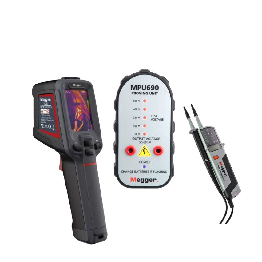
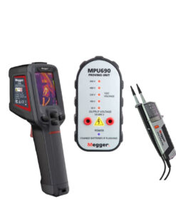
Three instruments, one complete electrician’s kit. Prove your TPT420 is working before you trust it — the MPU690 proving unit steps from 50 V to 690 V so your tester is always verified against a known source. The TPT420 reads live voltages up to 1000 V AC without tripping your RCDs. Then the TC256 256×192 thermal camera finds what the tester can’t: hot terminations, unbalanced phases, failing solar strings. All three ship ready to work. Quote today.
The three-step rule every electrician knows — and the kit that covers all of it
Working safely around live electrical equipment comes down to one principle that experienced sparks never skip: test before you touch, and prove your tester before you test. It sounds simple, but in practice it needs three instruments — a proving unit, a voltage tester, and something that can see faults under load that no meter will catch. The Megger Electrician Kit puts all three in one bundle, in the right order, from a brand Australian trades have relied on for a century.
Step one: prove the tester. The MPU690 Proving Unit generates five stepped voltages from 50 V to 690 V — no mains connection required — so you can verify the TPT420 is reading correctly against a known, controlled source before you put it near a live circuit. It’s the step that turns “I think my tester is working” into “I know my tester is working.”
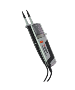
Step two: verify voltage. The TPT420 Two-Pole Voltage and Continuity Tester confirms whether a circuit is live or dead at up to 1000 V AC and 1500 V DC, with phase rotation indication, continuity testing to 500 kΩ, and a design that works below RCD trip thresholds so you’re not nuisance-tripping breakers mid-inspection. If there’s no battery left, it still warns of dangerous voltage — because safety that depends on a fresh battery isn’t good enough.
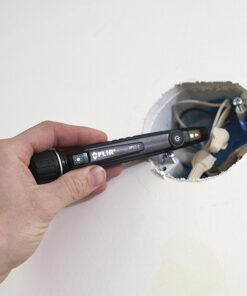
Step three: find the faults you can’t measure. The TC256 256×192 Thermal Camera lets you scan live, loaded circuits and see what’s running hot. Loose terminations, phase imbalance, overloaded conductors, a tired solar string — they all show up as heat before they show up as a fault. The meter tells you what voltage is present; the camera tells you which connection is about to be the problem.
Together, these three instruments cover the complete safe-work and fault-detection workflow that serious Australian electricians run on every switchboard job, every solar installation, and every commercial maintenance contract.
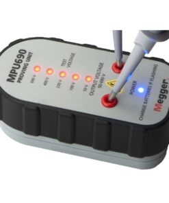
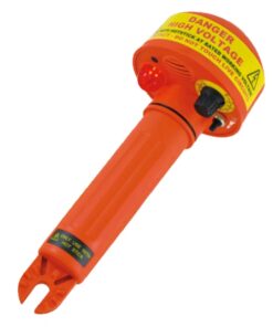
The MPU690: prove it before you trust it
There’s a reason Australian electrical safety guidelines and AS/NZS 4836 safe-working practices emphasise proving your test instrument against a known voltage source before relying on it for live-dead-live verification: a two-pole voltage tester that has a fault, depleted cells, or damaged leads will read “dead” on a live circuit. That’s not a near-miss — that’s a fatality risk.
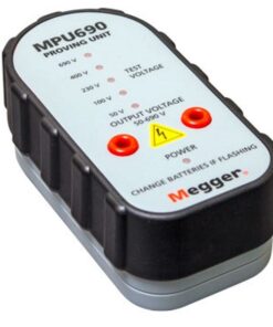
The MPU690 removes the uncertainty. It’s a compact, battery-operated voltage source — no mains connection, no access to a known live circuit required — that steps through five nominal output voltages: 50 V, 100 V, 230 V, 400 V and 690 V, covering every significant level in Australian single-phase (230 V) and three-phase (400 V line-to-line) LV systems, as well as low-voltage DC and sub-50 V ELV circuits. At switch-on, it starts at 690 V and ramps down through each step automatically, with a dedicated LED confirming each level — so you can watch the TPT420 respond correctly at every voltage, not just one.
The MPU690 auto-powers on the instant the TPT420 probes are inserted, generating a 50 Hz output that genuinely simulates mains AC supply — including enough output power to correctly drive voltage indicators that use a lamp for indication, not just electronic testers. Six AA batteries power the unit, delivering enough capacity for extensive field use between changes, and a rugged case with a magnetic base lets you stick it to a panel door or steel surface hands-free while you work. At 346 g and 130 × 68 × 48 mm it fits in a pocket.
One important note carried over from the Megger datasheet: the MPU690 is designed for two-pole voltage testers and voltage indicators — it is not recommended for use with multimeters.
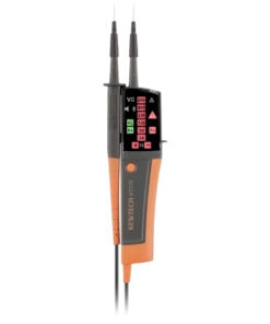
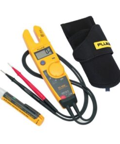
The TPT420: every voltage test an electrician needs, in one instrument
The TPT420 is Megger’s CAT IV 1000 V two-pole voltage and continuity tester — the instrument that answers “is this circuit live or dead?” and “is this path continuous?” on Australian single-phase 230 V and three-phase 415 V (400 V line-to-line) installations.
Reads both AC and DC, across every relevant range. 12–1000 V AC (with a 4-digit LCD reading to 1 V resolution) and 12–1500 V DC covers standard installation voltages, three-phase systems, solar PV string voltages and battery banks in the same instrument. A 13-LED display gives instant visual indication at key voltage bands alongside the LCD numeric readout.
Works below RCD trip thresholds — by design. When testing phase-to-earth on circuits protected by RCDs, RCBOs and safety breakers, the TPT420 is engineered to draw less than the trip threshold — so you get the reading you need without nuisance-tripping the protective device and losing power to the whole board.
Phase rotation without crossing probes. The simplified phase rotation indication (120–400 V phase-to-phase, 50/60 Hz) tells you phase sequence on a three-phase circuit without the fiddly probe-crossing routine some older two-pole testers require — faster and with less chance of an accidental short.
Safety that doesn’t depend on the battery. The TPT420’s most important safety feature is what it does with no batteries at all: it still warns of dangerous voltage. Because the voltage warning function operates passively — not via the battery — a tester with flat cells won’t silently read zero on a live circuit. That’s the feature that matters most on a job where someone else changed the batteries last.
Continuity with ears and eyes. The 0–500 kΩ continuity function provides both visual (LED) and acoustic indication, and the 40–400 Hz frequency range covers 50 Hz mains as well as fire alarm and other systems. GS38-compliant probe tip shrouds are supplied as standard for safe contact with Australian switchgear. An integrated LED torch rounds out the package for dark risers, roof cavities and meter boxes.
The TPT420 ships in a protective carry pouch (1013-189), weighs 207 g, and runs on two AAA batteries.
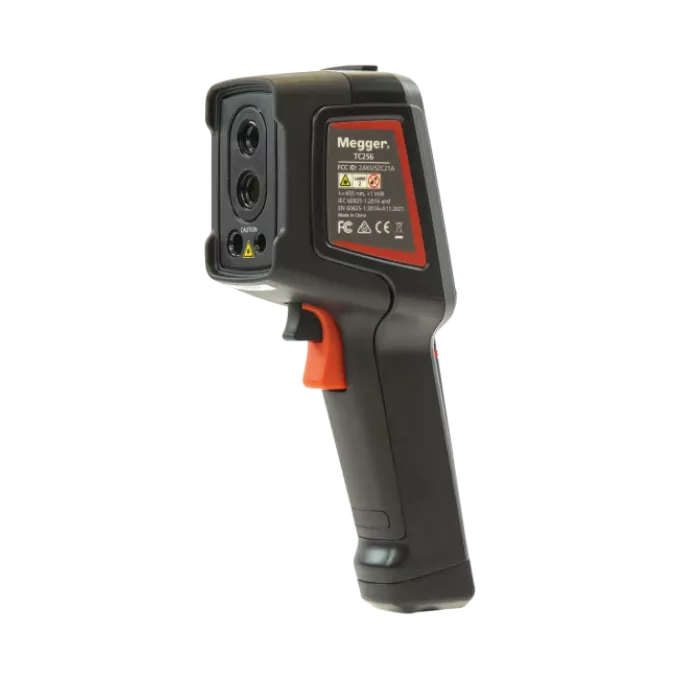
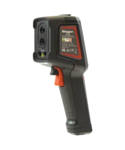
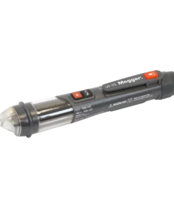
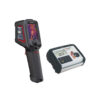
The TC256: see the fault before it becomes a callout
A voltage tester confirms what’s happening on a de-energised or safely isolated circuit. A thermal camera tells you what’s developing on the live, loaded system — and that’s an entirely different category of information.
The TC256 is a 256×192 infrared thermal camera with 45 mK thermal sensitivity and real-time super-resolution to 512×384, turning invisible heat into a clear, measurable image. Point it at a live 415 V distribution board and a loose or corroded termination shows up as a defined hot spot — not a vague smudge — separated from its neighbours by temperature differences the 45 mK NETD can resolve to under a tenth of a degree. Walk an energised solar PV array and hot cells, bypassed diodes and warming DC connectors stand out against healthy strings. Scan a motor control centre and failing contactors, overloaded cable runs and imbalanced phases announce themselves before a nuisance trip or burnout.
Four imaging modes (pure IR, visible light, picture-in-picture, and multi-image fusion) let you tie every thermal anomaly to the exact asset in the visible scene — no guessing which breaker or which cable gland in your report. Six colour palettes, a centre-spot measurement plus three fixed areas, adjustable emissivity and threshold alarms cover the analysis needs of routine electrical inspections through to solar O&M and industrial plant maintenance. A measurement range of -20 °C to 550 °C (auto-switching) handles everything from underfloor heating to heavily loaded busbars.
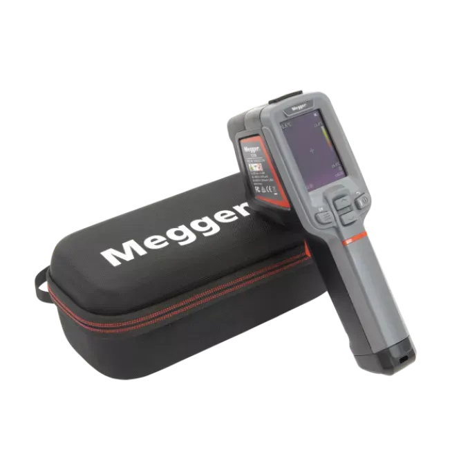
At ~11 hours battery life, IP54, 2 m drop rating, 16 GB storage, and WiFi plus app reporting, it’s built for full-day site work. The TC256 ships with an AU plug adaptor and a calibration certificate. (Full TC256 specifications are on the individual TC256 product page.)
The complete electrician’s workflow in three steps
Used together on every job, this kit covers the complete safe-work and fault-detection sequence:
- Before touching anything — prove the tester. Plug the TPT420 into the MPU690. Watch it step through 50, 100, 230, 400 and 690 V. You now know your tester is reading accurately, the probes are sound and the leads aren’t open-circuit. Takes under 60 seconds. This step is the live-dead-live protocol’s silent first move.
- Approach the circuit — verify voltage. Apply the TPT420 to confirm the circuit is de-energised (or live, as the case may be), check phase rotation on your three-phase supply, confirm RCD circuits without tripping them, and verify continuity of protective conductors. Safe, fast, fully instrumented.
- Re-energise and scan thermally. With the system back under real load, sweep the TC256 across the switchboard, busbars, solar array or plant in a single pass. Any connection running hotter than it should lights up before it becomes a fault. Schedule the repair before the emergency happens.
That three-step sequence is the practical difference between reactive maintenance and professional, defensible electrical work — and this kit provides every instrument it requires.
Built for Australian trade work
The TPT420 conforms to IEC/EN 61243-3:2014 and DIN VDE 0682-401 — the current international standards for two-pole voltage testers — and is rated CAT IV 1000 V, the highest overvoltage category for testing at the origin of an installation. GS38-compliant probe shrouds are included as standard. The MPU690’s 50 V, 100 V, 230 V, 400 V and 690 V output steps map directly to the voltage levels electricians encounter in Australian LV systems: single-phase 230 V, three-phase 400 V line-to-line, and industrial 690 V equipment. The TC256 arrives with an AU plug adaptor and a calibration certificate from the factory.
As with all Megger instruments, keeping your testing equipment on a NATA-traceable recalibration cycle ensures your measurements carry a recognised chain of accuracy — critical for compliance documentation, insurance and audit purposes under AS/NZS 3000 and AS/NZS 3017 regimes.
What’s in the Kit
| Item | Part No. | Role in the Workflow |
|---|---|---|
| Megger TC256 256×192 Thermal Camera | 1016-972 | Step 3 — predictive fault-finding on live, loaded systems |
| Megger TPT420 Two-Pole Voltage & Continuity Tester | 1013-189 | Step 2 — live/dead verification, phase rotation, continuity |
| Megger MPU690 Proving Unit | 1001-561 | Step 1 — prove the tester before you trust it |
| TPT420 supplied with | — | Carry pouch, GS38 shrouds, 2 × AAA batteries |
| TC256 supplied with | — | Rigid case, wrist strap, power adapter (with AU plug adaptor), USB-C cable, quick start guide, calibration certificate |
| MPU690 supplied with | — | 6 × AA batteries |
Technical Specifications — TPT420 Two-Pole Voltage & Continuity Tester
| Specification | Value | Why It Matters |
|---|---|---|
| AC voltage range | 12–1000 V AC | Covers ELV through to full CAT IV LV installation voltages |
| DC voltage range | 12–1500 V DC | Solar PV string voltages, batteries, DC supply systems |
| Display | 13 LEDs + 4-digit LCD (1 V resolution) | Instant band indication plus precise numeric readout simultaneously |
| Voltage warning (no battery) | Yes — passive voltage warning below 50 V AC / 120 V DC | Warns of dangerous voltage even with flat batteries — the feature that matters most |
| Frequency range | 40–400 Hz | 50 Hz mains, fire alarm, generator and other system frequencies |
| Single-pole voltage test | 100–1000 V AC (50/60 Hz) | Quick single-probe indication when two-pole access isn’t practical |
| Phase rotation | 120–400 V phase-to-phase, AC 50/60 Hz | Three-phase sequence check without crossing test probes |
| Continuity range | 0–500 kΩ | Tests protective conductors and bonding paths with visual + audible indication |
| RCD / RCBO safe | Yes — operates below tripping threshold | No nuisance trips when testing phase-to-earth on protected circuits |
| Peak current | <3.5 mA @ 1000 V | Safe for sensitive electronic circuits |
| Safety rating | CAT IV 1000 V, Pollution Degree 2 | Rated for testing at the origin of the installation |
| Standards compliance | IEC/EN 61243-3:2014, DIN VDE 0682-401, EN 61010 | Current international standards for two-pole voltage testers |
| Ingress protection | IP64 | Dust-tight and splash-resistant for site use |
| Integrated torch | Yes — LED | Visibility in dark risers, roof spaces and meter boxes |
| Backlight | Automatic | Readable in low light without a button press |
| Polarity indication | Automatic | DC polarity identified without manual selection |
| Cable length | ~1.2 m | Enough reach for panel work without excessive lead management |
| Power supply | 2 × AAA (LR03) alkaline | Standard cells, easy to source on any site |
| Operating temperature | -5 °C to 40 °C | Rated for Australian site conditions |
| Dimensions / weight | 255 × 67 × 30 mm / ~207 g | Slim, lightweight — fits a tool belt pouch comfortably |
| In the box | TPT420, carry pouch, GS38 shrouds, 2 × AAA batteries | Site-ready, GS38-compliant out of the box |
| Part number | 1013-189 | — |
Technical Specifications — MPU690 Proving Unit
| Specification | Value | Why It Matters |
|---|---|---|
| Output voltages | 50 V, 100 V, 230 V, 400 V, 690 V (5 steps) | Covers ELV through to full 690 V industrial LV — including 230 V and 400 V Australian mains levels |
| Output sequence | Auto: starts at 690 V, ramps down step by step to off | Verifies tester response across all voltage bands in one cycle |
| Power-on mode | Automatic — activates when probes are inserted | No manual switch; instant proving when probes engage |
| Output frequency | 50 Hz (simulates AC mains) | Genuine mains simulation, including lamp-type voltage indicators |
| Maximum output | 10 W | Enough to correctly drive test-lamp type voltage indicators |
| Voltage indicators | 5 LEDs (one per voltage step) + power/low battery LED | Visual confirmation of each voltage step and battery status |
| Power supply | 6 × AA (LR06) alkaline | Long battery life; standard cells available everywhere |
| Magnetic base | Yes | Hands-free placement on panel doors, steel surfaces, cable trays |
| Case | Rugged moulded case | Survives daily tool-bag life |
| Operating temperature | -10 °C to +40 °C | Rated for Australian outdoor and site conditions |
| Dimensions / weight | 130 × 68 × 48 mm / 346 g | Compact enough for a tool belt, heavy enough to sit stable |
| Compatibility | Two-pole voltage testers and voltage indicators (not for use with multimeters) | Paired specifically with the TPT420 |
| Part number | 1001-561 | — |
Technical Specifications — TC256 Thermal Camera (Summary)
| Specification | Value | Why It Matters |
|---|---|---|
| IR resolution | 256 × 192 (super-resolution 512 × 384) | Defines early-stage faults entry-level imagers blur out |
| Thermal sensitivity (NETD) | 45 mK | Resolves sub-0.1 °C temperature differences |
| Temperature range | -20 °C to 550 °C (auto-switching) | Covers refrigeration through to heavily loaded busbars |
| Accuracy | ±2 °C or ±2% | Reliable for trending and pass/fail decisions |
| Image modes | IR, Visible Light, PIP, Multi-Image Fusion | Ties every hot spot to the exact asset |
| Connectivity | USB-C, WiFi, Thermography app (iOS/Android), 16 GB storage | Site reporting and desktop analysis |
| Battery | ~11 hours; USB-C charging (charge while using) | Full working day on one charge |
| Environmental | IP54, 2 m drop rated | Built for real site conditions |
| In the box | Camera, rigid case, wrist strap, power adapter with AU plug adaptor, USB-C cable, quick start guide, calibration certificate | Ready to scan out of the box |
| Part number | 1016-972 | — |
Full TC256 specifications: see the individual TC256 product page.
Applications & Use Cases
Switchboard inspection and maintenance — single-phase and three-phase. Prove the TPT420 on the MPU690 before you approach. Use the TPT420 to confirm dead (or live), check phase rotation on the 415 V three-phase supply, and test continuity of protective conductors without tripping RCDs. Re-energise and sweep the live board with the TC256 to catch any hot terminations, loose lugs or overloaded conductors that passed the static tests. Document everything: the tester reading, the continuity result, and the thermal image in the same site report.
New installation and handover testing — AS/NZS 3000 / AS/NZS 3017. The TPT420’s live/dead verification step is fundamental to any safe installation test sequence. The TC256 complements AS/NZS 3017 inspection requirements by providing thermal evidence that the live installation is running correctly under load — a step no megohmmeter or continuity tester can replicate.
Solar PV commissioning and O&M — AS/NZS 5033. Verify string voltages at the combiner and inverter DC input with the TPT420’s 1500 V DC capability. Then scan the live array with the TC256 to identify hot cells, bypassed diodes, mismatched strings and warming DC connectors and isolators. The proven TPT420 + TC256 combination covers both the electrical and thermal dimensions of a PV system inspection.
Industrial and commercial plant maintenance. Prove the tester, check voltage at MCC and distribution switchboards with the TPT420, then thermally scan MCCs, cable trays, motor terminals, contactors and busbars with the TC256. The 690 V output on the MPU690 confirms the TPT420 reads correctly at industrial supply voltages too. Supports AS ISO 55000 asset management and condition-based maintenance practice.
Live-dead-live verification for licensed electricians. The TPT420 + MPU690 combination is the textbook implementation of safe-approach testing: prove the tester on the MPU690 (first live test), test the circuit with the TPT420, then re-prove on the MPU690 to confirm the tester still reads correctly after the test (second live test). Fast, straightforward, fully documented.
HVAC, fire alarm, and automotive diagnostics. The TPT420’s 40–400 Hz frequency range and 12–1500 V DC capability make it useful beyond pure electrical installation work — fire alarm panel voltages, automotive systems and variable-frequency drive outputs all fall within its range.
TAFE and RTO training. A complete, logical three-instrument set that teaches the correct proving-and-testing workflow, with the TC256 adding thermographic inspection skills to the training program.
| Weight | .5 kg |
|---|
Be the first to review “Megger Electrician Kit | TC256 + TPT420 + MPU690 | Australia”
You must be logged in to post a review.
Technical Specifications — TPT420 Two-Pole Voltage & Continuity Tester
| Specification | Value | Why It Matters |
|---|---|---|
| AC voltage range | 12–1000 V AC | Covers ELV through to full CAT IV LV installation voltages |
| DC voltage range | 12–1500 V DC | Solar PV string voltages, batteries, DC supply systems |
| Display | 13 LEDs + 4-digit LCD (1 V resolution) | Instant band indication plus precise numeric readout simultaneously |
| Voltage warning (no battery) | Yes — passive voltage warning below 50 V AC / 120 V DC | Warns of dangerous voltage even with flat batteries — the feature that matters most |
| Frequency range | 40–400 Hz | 50 Hz mains, fire alarm, generator and other system frequencies |
| Single-pole voltage test | 100–1000 V AC (50/60 Hz) | Quick single-probe indication when two-pole access isn’t practical |
| Phase rotation | 120–400 V phase-to-phase, AC 50/60 Hz | Three-phase sequence check without crossing test probes |
| Continuity range | 0–500 kΩ | Tests protective conductors and bonding paths with visual + audible indication |
| RCD / RCBO safe | Yes — operates below tripping threshold | No nuisance trips when testing phase-to-earth on protected circuits |
| Peak current | <3.5 mA @ 1000 V | Safe for sensitive electronic circuits |
| Safety rating | CAT IV 1000 V, Pollution Degree 2 | Rated for testing at the origin of the installation |
| Standards compliance | IEC/EN 61243-3:2014, DIN VDE 0682-401, EN 61010 | Current international standards for two-pole voltage testers |
| Ingress protection | IP64 | Dust-tight and splash-resistant for site use |
| Integrated torch | Yes — LED | Visibility in dark risers, roof spaces and meter boxes |
| Backlight | Automatic | Readable in low light without a button press |
| Polarity indication | Automatic | DC polarity identified without manual selection |
| Cable length | ~1.2 m | Enough reach for panel work without excessive lead management |
| Power supply | 2 × AAA (LR03) alkaline | Standard cells, easy to source on any site |
| Operating temperature | -5 °C to 40 °C | Rated for Australian site conditions |
| Dimensions / weight | 255 × 67 × 30 mm / ~207 g | Slim, lightweight — fits a tool belt pouch comfortably |
| In the box | TPT420, carry pouch, GS38 shrouds, 2 × AAA batteries | Site-ready, GS38-compliant out of the box |
| Part number | 1013-189 | — |
Technical Specifications — MPU690 Proving Unit
| Specification | Value | Why It Matters |
|---|---|---|
| Output voltages | 50 V, 100 V, 230 V, 400 V, 690 V (5 steps) | Covers ELV through to full 690 V industrial LV — including 230 V and 400 V Australian mains levels |
| Output sequence | Auto: starts at 690 V, ramps down step by step to off | Verifies tester response across all voltage bands in one cycle |
| Power-on mode | Automatic — activates when probes are inserted | No manual switch; instant proving when probes engage |
| Output frequency | 50 Hz (simulates AC mains) | Genuine mains simulation, including lamp-type voltage indicators |
| Maximum output | 10 W | Enough to correctly drive test-lamp type voltage indicators |
| Voltage indicators | 5 LEDs (one per voltage step) + power/low battery LED | Visual confirmation of each voltage step and battery status |
| Power supply | 6 × AA (LR06) alkaline | Long battery life; standard cells available everywhere |
| Magnetic base | Yes | Hands-free placement on panel doors, steel surfaces, cable trays |
| Case | Rugged moulded case | Survives daily tool-bag life |
| Operating temperature | -10 °C to +40 °C | Rated for Australian outdoor and site conditions |
| Dimensions / weight | 130 × 68 × 48 mm / 346 g | Compact enough for a tool belt, heavy enough to sit stable |
| Compatibility | Two-pole voltage testers and voltage indicators (not for use with multimeters) | Paired specifically with the TPT420 |
| Part number | 1001-561 | — |
Technical Specifications — TC256 Thermal Camera (Summary)
| Specification | Value | Why It Matters |
|---|---|---|
| IR resolution | 256 × 192 (super-resolution 512 × 384) | Defines early-stage faults entry-level imagers blur out |
| Thermal sensitivity (NETD) | 45 mK | Resolves sub-0.1 °C temperature differences |
| Temperature range | -20 °C to 550 °C (auto-switching) | Covers refrigeration through to heavily loaded busbars |
| Accuracy | ±2 °C or ±2% | Reliable for trending and pass/fail decisions |
| Image modes | IR, Visible Light, PIP, Multi-Image Fusion | Ties every hot spot to the exact asset |
| Connectivity | USB-C, WiFi, Thermography app (iOS/Android), 16 GB storage | Site reporting and desktop analysis |
| Battery | ~11 hours; USB-C charging (charge while using) | Full working day on one charge |
| Environmental | IP54, 2 m drop rated | Built for real site conditions |
| In the box | Camera, rigid case, wrist strap, power adapter with AU plug adaptor, USB-C cable, quick start guide, calibration certificate | Ready to scan out of the box |
| Part number | 1016-972 | — |
What’s included in the Megger Electrician Kit? The kit combines three instruments: the Megger TC256 256×192 thermal camera (part 1016-972), the Megger TPT420 two-pole voltage and continuity tester (part 1013-189), and the Megger MPU690 proving unit (part 1001-561). The TPT420 ships with a carry pouch, GS38 probe shrouds and AAA batteries; the TC256 with a rigid case, AU plug adaptor, USB-C cable and calibration certificate; the MPU690 with six AA batteries.
Why do I need a proving unit — isn’t the TPT420 self-testing? The TPT420 does indicate its own battery status, but a low-battery warning doesn’t prove the voltage measurement circuit is working correctly. A proving unit tests the complete instrument — voltage circuit, leads, probes and display — against a known, controlled voltage source. This is the “live-dead-live” protocol used in Australian safe-work practice and referenced in AS/NZS 4836, and it’s the only way to be confident your tester is reading correctly before you rely on a “dead” indication near a live circuit.
What voltage steps does the MPU690 prove? Five: 50 V, 100 V, 230 V, 400 V and 690 V. It auto-starts at 690 V and steps down automatically. The 230 V and 400 V steps map directly to Australian single-phase and three-phase LV supply voltages, and the 690 V step proves the tester at industrial distribution voltage. The MPU690 is not recommended for use with multimeters — it’s designed for two-pole voltage testers like the TPT420.
Does the TPT420 trip RCDs and RCBOs during testing? No — the TPT420 is specifically designed to draw current below the trip threshold of RCDs, RCBOs and safety breakers when testing between phase and earth. It also draws a peak current of less than 3.5 mA at 1000 V, making it safe for circuits with sensitive protection devices.
What happens if the TPT420’s batteries go flat on site? It still warns of dangerous voltage. The passive voltage warning function operates independently of the battery, so a tester with completely exhausted cells still indicates the presence of hazardous live voltage on the LED display. This is one of the TPT420’s most important safety features and a key reason it’s specified for professional electricians rather than a basic voltage pen.
Can the TPT420 test solar PV DC voltages? Yes. Its DC range extends to 1500 V DC, covering residential and commercial PV string voltages at the combiner and inverter DC input. The TC256 complements this with thermal imaging of the live array to find hot cells, faulty bypass diodes and warming DC connectors that electrical measurement alone won’t reveal.
Does the TC256 include an Australian plug adaptor? Yes — the TC256 ships with a power adapter that includes an AU plug adaptor, so it’s ready for a standard Australian GPO out of the box. It also comes with a calibration certificate. Megger recommends annual recalibration; keep it NATA-traceable through your supplier for compliance-grade documentation.
Is this kit suitable for industrial 690 V systems? The MPU690 outputs 690 V to verify the TPT420 at industrial supply voltage, and the TPT420 itself is rated CAT IV 1000 V — the highest overvoltage category for work at the origin of an installation. The TC256’s 550 °C temperature ceiling covers heavily loaded busbars and motor terminals. Together, the kit handles industrial LV environments confidently.
Electrical Testers
Electrical Testers
Electrical Testers
AC only Clamps Related Products


Next day delivery
Finance services
Price Match
Technical support
Product training
Calibration servises
Need help? Call our support team 1800 358 531
Reviews
There are no reviews yet.